Category: Class 10
Difference Between Concave Convex Lens
Difference Between Concave Convex Lens: Lenses are essential optical components that play a crucial role in various optical devices, including cameras, telescopes, microscopes, and eyeglasses.
Among the different types of lenses, concave and convex lenses are two primary categories, each with distinct properties and applications. In this article, we will delve into the key differences between concave and convex lenses, their shapes, characteristics, and applications.

Difference Between Concave Convex Lens
Concave Lens:
1. Shape and Structure:
- A concave lens is thinner at the center and thicker at the edges. It curves inward, resembling a cave or a bowl.
- The lens has two curved surfaces: one concave (curving inward) and one flat.
2. Light Refraction:
- When parallel rays of light pass through a concave lens, they diverge or spread apart.
- The point from which the diverging rays appear to originate is called the focal point (F), which is on the same side as the object.
3. Image Formation:
- A concave lens forms virtual, upright, and diminished images for real objects placed beyond its focal point.
- It can also create a virtual image for an object placed between the lens and its focal point.
4. Applications:
- Concave lenses are commonly used in corrective eyeglasses to treat nearsightedness (myopia).
- They are also used in devices like movie projectors to spread out the light from a small source and create a larger image.
Convex Lens:
1. Shape and Structure:
- A convex lens is thicker at the center and thinner at the edges. It bulges outward, resembling a lentil or a magnifying glass.
- The lens also has two curved surfaces: one convex (curving outward) and one flat.
2. Light Refraction:
- When parallel rays of light pass through a convex lens, they converge or come together.
- The point where the converging rays meet is called the focal point (F), which is on the opposite side of the object.
3. Image Formation:
- A convex lens forms real, inverted, and magnified images for objects placed beyond its focal point.
- It can also create virtual, upright, and magnified images for objects placed between the lens and its focal point.
4. Applications:
- Convex lenses are widely used in eyeglasses to correct farsightedness (hyperopia) and presbyopia.
- They are essential components in cameras, telescopes, and microscopes for focusing and magnifying distant or small objects.
Key Differences:
- Shape: Concave lenses are thinner at the center and thicker at the edges, while convex lenses are thicker at the center and thinner at the edges.
- Light Refraction: Concave lenses diverge incoming light rays, while convex lenses converge them.
- Focal Point: In concave lenses, the focal point is on the same side as the object, while in convex lenses, it is on the opposite side.
- Image Formation: Concave lenses produce virtual and diminished images for objects beyond the focal point, while convex lenses create real and magnified images for such objects.
- Applications: Concave lenses are used for correcting nearsightedness and in devices like projectors. Convex lenses are used for correcting farsightedness and in optical instruments like cameras, telescopes, and microscopes.
In summary, concave and convex lenses have distinct shapes, behaviors, and applications in optics. Their ability to refract light in different ways makes them invaluable in a wide range of optical systems and corrective lenses, enhancing our ability to see and manipulate the world around us.
Read More
- Difference Between Electric Field And Magnetic Field
- Difference Between Transducer And Sensor
- Difference Between Alternator And Generator
- Physical & chemical properties of water
- Difference Between Fuse And Circuit Breaker
Frequently Asked Questions (FAQs) Difference Between Concave Convex Lens
1. What are concave and convex lenses primarily used for?
Concave lenses are often used in eyeglasses to correct nearsightedness, while convex lenses are used to correct farsightedness. Both types are used in various optical devices, including cameras, telescopes, and microscopes.
2. How do concave and convex lenses differ in their shape and curvature?
Concave lenses are thinner at the center and thicker at the edges, curving inward. Convex lenses are thicker at the center and thinner at the edges, bulging outward.
3. What happens to light when it passes through a concave lens?
When parallel rays of light pass through a concave lens, they diverge or spread apart. This lens is known for causing light to diverge.
4. What is the focal point, and how does it differ for concave and convex lenses?
The focal point is the point where parallel rays of light either converge or appear to diverge from after passing through the lens. For concave lenses, the focal point is on the same side as the object, while for convex lenses, it is on the opposite side.
5. How do concave and convex lenses differ in terms of image formation?
Concave lenses form virtual, upright, and diminished images for real objects placed beyond the focal point. Convex lenses form real, inverted, and magnified images for objects beyond their focal point.
Difference Between Electric Field And Magnetic Field
Difference Between Electric Field And Magnetic Field: In the realm of electromagnetism, two fundamental concepts are at play: the electric field and the magnetic field.
These fields are essential for understanding the behavior of charged particles and the interaction between electricity and magnetism. In this article, we’ll explore the key differences between electric fields and magnetic fields and how they shape the world of physics and technology.

Difference Between Electric Field And Magnetic Field
1. Introduction
1.1 What is an Electric Field?
An electric field (E) is a spatial area surrounding an electrically charged object in which another charged object encounters a force. Electric fields arise from electric charges, whether they are positively or negatively charged, and they apply a force to other charged particles contingent upon their charge and the field’s intensity.
1.2 What is a Magnetic Field?
A magnetic field (B) is a defined region in space surrounding either a magnetic object or a moving charged particle where magnetic forces come into play. These magnetic fields originate from diverse sources, encompassing the presence of magnets, the motion of electrically charged particles, and the circulation of electric currents.
2. Nature of Fields
2.1 Electric Field:
- Electric fields are produced by electric charges.
- They are always present, whether or not there are other charges nearby.
- Electric field lines start from positive charges and terminate at negative charges.
- Electric field lines are radially outward from positive charges and radially inward toward negative charges.
- Electric fields can do work on charged particles, causing them to move along the field lines.
2.2 Magnetic Field:
- Magnetic fields are created through the action of magnets, the motion of electrically charged particles, and the presence of electric currents.
- Magnetic fields form closed loops, with no magnetic monopoles (separate north or south poles).
- They only exist in the presence of moving charges or currents.
- Magnetic field lines are continuous loops, never starting or ending.
- Magnetic fields can exert forces on moving charged particles but cannot do work on stationary charged particles.
3. Sources of Fields
3.1 Electric Field Sources:
- Electric fields are produced by stationary electric charges, both positive and negative.
- Objects that have an excess or deficit of electrons create electric fields.
3.2 Magnetic Field Sources:
- Magnetic fields are generated by magnets, such as permanent magnets and electromagnets.
- Moving electric charges, such as current-carrying wires, also produce magnetic fields.
4. Interaction with Charged Particles
4.1 Electric Field Interaction:
- Electric fields exert forces on charged particles, causing them to accelerate or move in the direction of the field lines.
- Charged particles can gain or lose electrical potential energy when moving in an electric field.
4.2 Magnetic Field Interaction:
- Magnetic fields exert forces only on moving charged particles (currents).
- The force experienced by a moving charged particle is perpendicular to both its velocity and the magnetic field direction.
- Magnetic fields do not perform work on stationary charged particles.
5. Mathematical Representation
5.1 Electric Field Representation:
- Electric fields are typically denoted and represented using vectors labeled as (E).
- The electric field at a specific point is mathematically expressed as E = F/q, where F represents the force encountered by a test charge (q) positioned within that field.
5.2 Magnetic Field Representation:
- Magnetic fields are represented by vectors (B).
- The magnetic field at a point is given by B = (μ₀/4π) * (I x r^2), where μ₀ is the permeability of free space, I is the current, and r is the distance from the current-carrying wire.
6. Applications
6.1 Electric Field Applications:
- Electric fields are essential in electronics, from powering household appliances to charging mobile devices.
- Capacitors store electric energy using electric fields.
- Electric fields are crucial in electrostatic applications, such as inkjet printers and photocopiers.
6.2 Magnetic Field Applications:
- Magnetic fields are fundamental to the operation of electric motors and generators.
- Magnetic fields are instrumental in the field of medical diagnostics, notably in magnetic resonance imaging (MRI).
- Magnetic fields play a pivotal role in transportation systems such as particle accelerators and maglev trains.
Conclusion
In summary, electric fields and magnetic fields are distinct but interrelated aspects of electromagnetism. Electric fields arise from stationary electric charges and impose forces on charged particles, whereas magnetic fields originate from magnets and the movement of charges, influencing moving charged particles. Understanding these fields is pivotal in various scientific and technological domains, from electronics to medical imaging and transportation.
Read More
- Difference Between Transducer And Sensor
- Difference Between Alternator And Generator
- Physical & chemical properties of water
- Difference Between Fuse And Circuit Breaker
- Difference Between Electromagnet And Permanent Magnet
Frequently Asked Questions (FAQs) Difference Between Electric Field And Magnetic Field
1. What is the fundamental difference between electric fields and magnetic fields?
The primary difference is in their sources and interactions. Electric fields originate from stationary electric charges and exert forces on charged particles, while magnetic fields result from magnets, moving electric charges, or currents and affect moving charged particles.
2. Are electric fields and magnetic fields always present together?
Not necessarily. Electric fields can exist independently of magnetic fields and vice versa. They are distinct phenomena, although they often interact in certain situations, such as in electromagnetic waves.
3. How do electric and magnetic fields interact in electromagnetic waves?
In electromagnetic waves, changing electric fields create changing magnetic fields, and vice versa. This interplay allows for the propagation of electromagnetic radiation, such as light and radio waves.
4. Do electric fields and magnetic fields have the same units of measurement?
Certainly, electric fields and magnetic fields utilize separate units of measurement. Electric fields are denoted in volts per meter (V/m), while magnetic fields are conventionally measured in units of teslas (T) or gauss (G).
5. Can magnetic fields exert forces on stationary charged particles?
No, magnetic fields do not exert forces on stationary charged particles. They only affect moving charged particles due to their motion.
Difference Between Transducer And Sensor
Difference Between Transducer And Sensor: Transducers and sensors are both devices used in various fields to measure and convert physical quantities into electrical signals, but they have distinct functions and characteristics. Here’s a comparison of the key differences between transducers and sensors:
Difference Between Transducer And Sensor
1. Function:
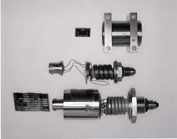
- Transducer: A transducer is a device that converts one form of energy or physical quantity into another. It can convert various types of energy, including mechanical, electrical, thermal, or optical, into electrical signals or vice versa.
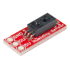
- Sensor: A sensor is a specific type of transducer that is designed to detect and respond to a particular physical stimulus, such as light, temperature, pressure, or motion. Sensors convert this stimulus into electrical signals for further processing or measurement.
2. Purpose:
- Transducer: Transducers are versatile devices used in a wide range of applications, from measuring physical quantities to converting signals for transmission or processing. They serve as intermediaries between different systems or devices.
- Sensor: Sensors are designed for specific purposes, such as detecting and measuring specific physical properties like temperature, humidity, or light. They provide data for monitoring and control systems.
3. Output:
- Transducer: Transducers can have various types of output, including voltage, current, resistance, or frequency. The output signal may not always be directly related to the measured physical quantity.
- Sensor: Sensors typically produce a well-defined electrical output signal that directly corresponds to the physical quantity they are designed to measure. For example, a temperature sensor generates an electrical signal proportional to the temperature.
4. Examples:
- Transducer: Examples of transducers include microphones (convert sound waves into electrical signals), speakers (convert electrical signals into sound waves), and strain gauges (convert mechanical strain into changes in electrical resistance).
- Sensor: Examples of sensors include temperature sensors (thermocouples or thermistors), light sensors (photodetectors), motion sensors (infrared motion detectors), and pressure sensors (piezoelectric sensors).
5. Sensing Element:
- Transducer: Transducers may or may not have a specific sensing element. Some transducers, like microphones and speakers, consist of multiple components and processes.
- Sensor: Sensors always include a dedicated sensing element that directly interacts with the physical stimulus to generate an electrical signal. For example, a temperature sensor uses a thermocouple as its sensing element.
6. Range of Application:
- Transducer: Transducers can have broad applications in various fields, including telecommunications, automation, audio technology, and instrumentation, where their primary function is to convert one form of energy into another.
- Sensor: Sensors are specialized for specific applications and are commonly used in areas such as environmental monitoring, industrial control systems, healthcare, and consumer electronics, where precise measurements of physical quantities are essential.
In summary, while both transducers and sensors play crucial roles in converting physical quantities into electrical signals, transducers are versatile devices used for various conversions, while sensors are specialized devices designed for specific measurements and applications.
Read More
- Difference Between Alternator And Generator
- Physical & chemical properties of water
- Difference Between Fuse And Circuit Breaker
- Difference Between Electromagnet And Permanent Magnet
- Blind Visually Impaired Optical Low Vision Aids
Frequently Asked Questions (FAQs) Difference Between Transducer And Sensor
1. What is a transducer?
A transducer is a device that converts one form of energy or physical quantity into another. It can convert various types of energy, including mechanical, electrical, thermal, or optical, into electrical signals or vice versa.
2. What is a sensor?
A sensor is a specific type of transducer designed to detect and respond to a particular physical stimulus, such as light, temperature, pressure, or motion. Sensors convert this stimulus into electrical signals for measurement or further processing.
3. How do transducers and sensors differ in their functions?
Transducers have a broader function, serving as intermediaries between different energy forms, while sensors are specialized for detecting and measuring specific physical properties.
4. What types of output signals do transducers and sensors produce?
Transducers can have various types of output signals, including voltage, current, resistance, or frequency, which may not always directly relate to the measured physical quantity. Sensors produce well-defined electrical output signals directly proportional to the measured property.
5. Can you provide examples of transducers and sensors?
Examples of transducers include microphones (converting sound waves into electrical signals), speakers (converting electrical signals into sound waves), and strain gauges (converting mechanical strain into changes in electrical resistance). Examples of sensors include temperature sensors (measuring temperature), light sensors (detecting light levels), and motion sensors (detecting motion or presence).
Difference Between Alternator And Generator
Difference Between Alternator And Generator: Alternators and generators are both devices that convert mechanical energy into electrical energy, but they operate on different principles and have distinct characteristics. Here’s a comparison of the key differences between alternators and generators:
Difference Between Alternator And Generator
1. Operating Principle:
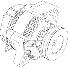
- Alternator: An alternator generates electricity using the principle of electromagnetic induction. It produces alternating current (AC), where the direction of current flow continuously reverses at a specific frequency.
- Generator: A generator, often referred to as a dynamo or DC generator, produces direct current (DC) through electromagnetic induction. It typically uses a commutator to convert alternating voltage into direct current.
2. Type of Current Produced:
- Alternator: Produces alternating current (AC), which periodically changes direction. The voltage and current alternate in polarity and direction.
- Generator: Produces direct current (DC), where the voltage and current flow consistently in one direction.
3. Output Voltage:
- Alternator: Alternators usually produce higher voltages (AC) suitable for many electrical applications. Voltage regulation is typically easier in alternators.
- Generator: Generators typically produce lower voltages (DC) and require additional components like voltage regulators to achieve stable output.
4. Maintenance:
- Alternator: Alternators generally require less maintenance compared to generators. They have fewer moving parts and do not have brushes and commutators, which wear out over time.
- Generator: Generators may require more maintenance due to the brushes and commutators that need periodic replacement. This maintenance can be more demanding and costly.
5. Efficiency:
- Alternator: Alternators are generally more efficient in converting mechanical energy into electrical energy. They are commonly used in modern vehicles due to their efficiency.
- Generator: Generators may have lower efficiency due to the energy losses associated with the commutator and the conversion of AC to DC.
6. Applications:
- Alternator: Alternators are widely used in automobiles to charge the battery and power electrical systems. They are also used in power generation stations to produce AC electricity.
- Generator: Generators are often found in smaller, portable applications, such as backup power sources, construction sites, and older electrical systems that require DC power.
7. Output Frequency:
- Alternator: Alternators produce AC with a specific frequency, usually 50 or 60 Hz, depending on the application and location.
- Generator: Generators do not have a fixed frequency; the output frequency depends on the rotational speed and design of the generator.
In summary, the primary difference between alternators and generators lies in the type of current they produce (AC vs. DC) and their operating principles. Alternators generate AC and are more efficient, while generators produce DC and may require more maintenance. The choice between them depends on the specific requirements of the application.
Read More
- Physical & chemical properties of water
- Difference Between Fuse And Circuit Breaker
- Difference Between Electromagnet And Permanent Magnet
- Blind Visually Impaired Optical Low Vision Aids
- Bar Magnet As An Equivalent Solenoid
Frequently Asked Questions (FAQs) Difference Between Alternator And Generator
1. What is the fundamental difference between an alternator and a generator?
The main difference lies in the type of current they produce. An alternator generates alternating current (AC), while a generator produces direct current (DC).
2. How do alternators and generators operate differently?
Alternators work on the principle of electromagnetic induction, producing AC through changing magnetic fields. Generators also use electromagnetic induction but typically employ a commutator to convert AC to DC.
3. Can you explain the output voltage differences between alternators and generators?
Alternators generally produce higher-voltage AC, while generators typically yield lower-voltage DC. Alternators may have built-in voltage regulation, making their output more stable.
4. Which one is easier to maintain, an alternator or a generator?
Alternators are generally easier to maintain because they have fewer moving parts and do not require components like brushes and commutators, which can wear out.
5. In terms of efficiency, which is better, an alternator or a generator?
Alternators are typically more efficient in converting mechanical energy into electrical energy compared to generators, which may have energy losses due to the commutator and AC-to-DC conversion.
Physical & chemical properties of water
Physical & chemical properties of water: Water is an extraordinary substance that is essential for life as we know it. Its unique physical and chemical properties make it a universal solvent, a critical component of biological processes, and a vital resource for our planet.
In this article, we will delve into the fascinating world of water and explore its distinct physical and chemical properties.

Physical & chemical properties of water
I. Physical Properties of Water
1. State of Matter:
- Water exists in all three states of matter under normal conditions. It can be found as a solid (ice), liquid (water), or gas (water vapor) depending on temperature and pressure.
2. High Heat Capacity:
- Water has a high specific heat capacity, meaning it can absorb and store a significant amount of heat energy without a substantial temperature change. This property helps regulate Earth’s temperature and climate.
3. High Heat of Vaporization:
- Water has a high heat of vaporization, requiring a considerable amount of energy to change from a liquid to a gas. This property is why sweating cools the body.
4. Density Anomaly:
- Water’s density decreases as it freezes, causing ice to float on water. This anomaly is vital for aquatic life, as it insulates bodies of water during freezing temperatures.
5. Cohesion and Adhesion:
- Water molecules exhibit strong cohesive forces, allowing them to stick together, and adhesive forces, allowing them to adhere to other surfaces. This property is responsible for capillary action in plants and the meniscus in a glass of water.
II. Chemical Properties of Water
1. Universal Solvent:
- Water is often referred to as the “universal solvent” because of its ability to dissolve a wide range of substances, including salts, acids, bases, and polar molecules. This property is crucial for chemical reactions in living organisms and natural processes.
2. Polarity:
- Water is a polar molecule, with an uneven distribution of electron density. This results in a positive and a negative end (dipole moment), making it an excellent solvent for polar compounds.
3. Hydrogen Bonding:
- Hydrogen bonding occurs between water molecules due to the attraction between the positively charged hydrogen atoms and the negatively charged oxygen atoms. This property gives water its high boiling point, surface tension, and adhesive properties.
4. Chemical Reactivity:
- Water can act as both an acid and a base (amphoteric), participating in chemical reactions as a proton donor (acid) or acceptor (base). It plays a crucial role in various chemical reactions, such as hydrolysis and ionization.
5. Ionization:
- Water molecules can ionize into hydronium ions (H3O+) and hydroxide ions (OH-) through autoionization. This process forms the basis of the pH scale and is fundamental to the chemistry of aqueous solutions.
Conclusion
Water’s physical and chemical properties are truly remarkable and underpin its significance in both the natural world and our daily lives. Its versatility as a solvent, its ability to moderate temperature, and its essential role in biochemical processes make water a precious resource. Understanding the unique properties of water is essential for fields ranging from biology and chemistry to environmental science and engineering.
Read More
- Difference Between Fuse And Circuit Breaker
- Difference Between Electromagnet And Permanent Magnet
- Blind Visually Impaired Optical Low Vision Aids
- Bar Magnet As An Equivalent Solenoid
- Equivalent Weight of KMnO4
Frequently Asked Questions (FAQs) Physical & chemical properties of water
1. What are the physical states of water at standard temperature and pressure?
Water can exist as a solid (ice), a liquid (water), and a gas (water vapor) under standard conditions.
2. Why does water have a high specific heat capacity?
Water has a high specific heat capacity because it can absorb and store a significant amount of heat energy without a substantial change in temperature. This property helps regulate Earth’s temperature and climate.
3. What is the heat of vaporization, and why is it important for water?
The heat of vaporization is the amount of energy required to change a substance from a liquid to a gas at a constant temperature. Water’s high heat of vaporization is important because it makes sweating an effective cooling mechanism for living organisms.
4. Can you explain the density anomaly of water?
Water’s density decreases as it freezes, causing ice to float on water. This anomaly is vital for aquatic life, as it insulates bodies of water during freezing temperatures.
5. What is the significance of water’s cohesion and adhesion properties?
Water’s cohesion allows its molecules to stick together, while adhesion allows them to adhere to other surfaces. These properties are responsible for capillary action in plants and the formation of the meniscus in containers.
Difference Between Fuse And Circuit Breaker
Difference Between Fuse And Circuit Breaker: Fuses and circuit breakers are both electrical safety devices designed to protect electrical circuits from overcurrents and short circuits, but they differ in how they operate and their resetability. Here’s a comparison of the key differences between fuses and circuit breakers:

Difference Between Fuse And Circuit Breaker
1. Operation:
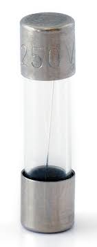
- Fuse: A fuse is a simple, one-time-use device that consists of a thin wire or metal strip that melts when exposed to excessive current. When the current exceeds a certain threshold, the fuse wire melts, breaking the circuit and disconnecting the power.
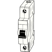
- Circuit Breaker: Circuit breakers are reusable devices that can be manually reset after they trip. They use an electromechanical mechanism to detect overcurrent or short-circuit conditions. When a fault occurs, the circuit breaker trips, opening the circuit to interrupt the current flow.
2. Resetability:
- Fuse: Fuses are not resettable. Once a fuse melts and interrupts the circuit, it needs to be replaced with a new fuse of the same rating.
- Circuit Breaker: Circuit breakers are resettable. After they trip due to a fault, they can be reset by flipping the breaker’s switch back to the “on” position, restoring power to the circuit.
3. Cost:
- Fuse: Fuses are generally less expensive than circuit breakers, but the cost adds up over time since they need to be replaced each time they blow.
- Circuit Breaker: Circuit breakers are more expensive upfront but offer long-term cost savings because they can be reset and reused.
4. Response Time:
- Fuse: Fuses typically have a faster response time than circuit breakers since they react almost instantly to overcurrent conditions.
- Circuit Breaker: Circuit breakers may have a slightly slower response time because of the mechanical components involved, but they are still effective in protecting against overcurrents.
5. Sensitivity:
- Fuse: Fuses are generally less sensitive to minor overcurrents and may not trip as quickly as circuit breakers in response to small faults.
- Circuit Breaker: Circuit breakers can be adjusted to different levels of sensitivity, allowing for better protection against a wider range of faults.
6. Lifespan:
- Fuse: Fuses have a limited lifespan and need replacement each time they blow.
- Circuit Breaker: Circuit breakers have a longer lifespan and can be used repeatedly as long as they are not damaged.
In summary, fuses and circuit breakers both serve the essential purpose of protecting electrical circuits, but they differ in their operation, resetability, cost, response time, sensitivity, and lifespan. The choice between them depends on the specific requirements of the electrical system and the desired level of protection.
Read More
- Difference Between Electromagnet And Permanent Magnet
- Blind Visually Impaired Optical Low Vision Aids
- Bar Magnet As An Equivalent Solenoid
- Equivalent Weight of KMnO4
- Molecular Mass of Na
Frequently Asked Questions (FAQs) Difference Between Fuse And Circuit Breaker
1. What is a fuse, and how does it work?
A fuse is an electrical safety device that consists of a thin wire or metal strip. It works by melting when exposed to excessive current, breaking the circuit and disconnecting the power.
2. What is a circuit breaker, and how does it work?
A circuit breaker is an electrical safety device that uses an electromechanical mechanism to detect overcurrent or short-circuit conditions. It trips by opening the circuit to interrupt the current flow.
3. Can fuses be reset after they blow?
No, fuses are one-time-use devices and cannot be reset. They need to be replaced with a new fuse of the same rating.
4. Can circuit breakers be reset after they trip?
Yes, circuit breakers are resettable. After they trip due to a fault, they can be manually reset by flipping the breaker’s switch back to the “on” position.
5. Which is more cost-effective, fuses, or circuit breakers?
Fuses are generally less expensive upfront than circuit breakers. However, circuit breakers offer long-term cost savings because they can be reset and reused, whereas fuses need replacement.
Difference Between Electromagnet And Permanent Magnet
Difference Between Electromagnet And Permanent Magnet: Electromagnets and permanent magnets are two distinct types of magnets with significant differences in their properties, generation, and applications. Here’s a breakdown of the key differences between them:
Difference Between Electromagnet And Permanent Magnet
1. Generation:
- Electromagnets: are magnetism on demand, formed by directing an electric current through a coiled wire. The presence of current generates a magnetic field, and once the current ceases, the magnetism promptly dissipates.
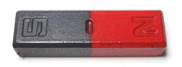
- Permanent Magnet: Permanent magnets are naturally occurring or man-made materials that retain their magnetism without the need for an external electric current. They have a persistent magnetic field.
2. Magnetic Strength:
- Electromagnet: The strength of an electromagnet can be easily adjusted by changing the amount of current passing through the coil. Strong electromagnets can be created for specific applications.
- Permanent Magnet: The strength of a permanent magnet is fixed and cannot be easily altered without demagnetizing or physically altering the magnet.
3. Durability:
- Electromagnet: Electromagnets are not as durable as permanent magnets since their magnetic properties depend on the presence of an electric current. When the current is interrupted, the magnetism disappears.
- Permanent Magnet: Permanent magnets are more durable and can maintain their magnetism for a long time under normal conditions.
4. Applications:
- Electromagnet: Electromagnets are commonly used in applications where the magnetic field needs to be controlled or switched on and off, such as in electric motors, solenoids, MRI machines, and magnetic locks.
- Permanent Magnet: Permanent magnets are used in various applications, including refrigerator magnets, magnetic compasses, speakers, hard drives, and generators.
5. Size and Shape:
- Electromagnets: Electromagnets offer flexibility in design, allowing for customization in terms of size and shape to suit specific application needs.
- Permanent Magnet: On the other hand, permanent magnets also come in various sizes and shapes, but their magnetic characteristics are inherently defined by the materials they are composed of.
6. Maintenance:
- Electromagnets: often necessitate routine maintenance to safeguard the integrity of the coil and its connections. Furthermore, their magnetism can diminish if the coil sustains damage or if there is a failure in the power source.
- Permanent Magnet: Permanent magnets generally require little to no maintenance as long as they are not subjected to extreme conditions that could demagnetize them.
In summary, the primary difference between electromagnets and permanent magnets lies in their generation, magnetic strength control, durability, and applications. Electromagnets derive their magnetism from an electric current, making them temporary magnets. In contrast, permanent magnets possess an inherent magnetic field and do not depend on external power sources to sustain their magnetism.
Read More
- Blind Visually Impaired Optical Low Vision Aids
- Bar Magnet As An Equivalent Solenoid
- Equivalent Weight of KMnO4
- Molecular Mass of Na
- Chemical Properties of Acid
Frequently Asked Questions (FAQs) On Difference Between Electromagnet And Permanent Magnet
1. What is an electromagnet?
An electromagnet is a temporary magnet created by passing an electric current through a coil of wire.
2. What is a permanent magnet?
A permanent magnet is a magnet that retains its magnetic properties without the need for an external electric current.
3. How are electromagnets and permanent magnets generated differently?
Electromagnets are generated by passing an electric current through a coil of wire, while permanent magnets are naturally occurring or man-made materials with intrinsic magnetic properties.
4. Can you control the strength of an electromagnet?
Yes, the strength of an electromagnet can be easily adjusted by changing the amount of current passing through the coil.
5. Can you control the strength of a permanent magnet?
No, the strength of a permanent magnet is fixed and cannot be easily altered without demagnetizing or physically altering the magnet.
Blind Visually Impaired Optical Low Vision Aids
Blind Visually Impaired Optical Low Vision Aids: Visual impairment, whether from birth or acquired later in life, presents unique challenges for individuals in their daily lives.
Tasks that many of us take for granted, such as reading a book, recognizing faces, or safely navigating the environment, can become significantly more difficult for those with visual impairments. However, advancements in technology and innovative assistive devices have greatly improved the quality of life for the blind and visually impaired. Among these aids, optical low vision aids play a crucial role in enhancing independence and accessibility.
This article delves into the world of optical low vision aids, explaining what they are, how they work, and their various types and applications. We’ll also explore how these aids are changing the lives of individuals with visual impairments and providing new opportunities for education, employment, and overall well-being.

Blind Visually Impaired Optical Low Vision Aids
Blind Visually Impaired Optical Low Vision Aids
Understanding Optical Low Vision Aids
Optical low vision aids are precisely engineered devices created to empower individuals who are blind or have visual impairments, enabling them to make the most of their remaining vision.. They use optical technology to magnify and enhance images, making them more accessible to those with visual impairments. These aids are indispensable tools that bridge the gap between standard eyeglasses or contact lenses and more complex vision restoration technologies like surgery or implants.
Types of Optical Low Vision Aids
There is a wide range of optical low vision aids available, each catering to specific visual needs and preferences. Here are some of the most common types:
- Magnifiers: Magnifiers use lenses to enlarge and enhance the appearance of objects. They come in various forms, such as handheld magnifiers, stand magnifiers, and illuminated magnifiers. Some are portable for on-the-go use, while others are designed for specific tasks like reading or viewing distant objects.
- Telescopes: Telescopic aids are designed to help individuals see distant objects more clearly. They are often used for activities like watching sports events, enjoying scenic views, or identifying objects at a distance.
- Electronic Magnification Devices: These devices, often referred to as video magnifiers or closed-circuit television (CCTV) systems, use cameras and displays to magnify printed materials or objects. Users can adjust the magnification level, contrast, and color settings to suit their needs.
- Wearable Aids: Some optical low vision aids are wearable and utilize cameras and displays to enhance the user’s vision. These devices can be particularly helpful for individuals with conditions like retinitis pigmentosa.
- Reading Glasses with Built-in Magnification: These are traditional-looking eyeglasses with magnifying lenses built into them, making it easier for individuals to read small print or engage in close-up tasks.
How Optical Low Vision Aids Work
- The basic principle behind optical low vision aids is the magnification of objects to make them more visible. Here’s a simplified explanation of how some of these aids work:
- Magnifiers: A magnifier uses a convex lens to bend and enlarge light, making objects appear larger and closer to the user’s eyes. The user positions the magnifier between their eyes and the object they want to see, adjusting the distance for optimal focus.
- Telescopes: Telescopic aids use a combination of lenses to bring distant objects into focus. Users can adjust the eyepiece or settings to achieve the desired magnification.
- Electronic Magnification Devices: These devices capture an image using a camera, display it on a screen, and allow the user to zoom in, change contrast, and apply other settings to enhance visibility.
- Wearable Aids: Wearable devices, such as electronic glasses, employ cameras to capture real-time video and project it onto screens positioned in front of the user’s eyes. These screens are customizable, allowing users to adjust settings for magnification and contrast to suit their specific visual preferences.
Applications and Impact
Optical low vision aids have a profound impact on the lives of individuals with visual impairments:
- Education: These aids enable students with visual impairments to access textbooks, study materials, and classroom presentations more easily. They promote independent learning and academic success.
- Employment: Many individuals with visual impairments use optical low vision aids to perform tasks at work, enhancing their job performance and career opportunities.
- Daily Living: Optical low vision aids assist with everyday activities such as reading, cooking, recognizing faces, and safely navigating unfamiliar environments.
- Leisure and Hobbies: These aids empower individuals to pursue hobbies like reading, watching TV, knitting, or enjoying outdoor activities with greater ease and enjoyment.
- Social Engagement: Enhanced vision fosters better social interaction, allowing individuals to recognize friends and family, read expressions, and engage in social activities.
- Healthcare: Optical aids help individuals manage their health by reading medication labels, monitoring their vital signs, and accessing healthcare information.
Consulting a Low Vision Specialist
While certain optical low vision aids are available for purchase without a prescription, it is highly recommended that individuals with visual impairments seek consultation with an eye care professional or a low vision specialist. These specialized professionals can offer tailored advice and recommend the most appropriate aids, including prescribing specific devices that align with the individual’s unique needs and requirements.
Conclusion
Optical low vision aids have revolutionized the lives of individuals who are blind or visually impaired. These devices enhance independence, accessibility, and overall quality of life by making the most of the user’s remaining vision. As technology continues to advance, the future looks brighter for individuals with visual impairments, offering them new opportunities. Experiences previously thought impossible.
Read More
- Bar Magnet As An Equivalent Solenoid
- Equivalent Weight of KMnO4
- Molecular Mass of Na
- Chemical Properties of Acid
- Molar Mass of Benzene
Frequently Asked Questions (FAQs) Blind Visually Impaired Optical Low Vision Aids
What are optical low vision aids for the blind and visually impaired?
Optical low vision aids are devices designed to assist individuals who are blind or visually impaired in enhancing their remaining vision. These aids use optical technology to magnify and enhance images, making them more accessible to those with visual impairments.
Who can benefit from optical low vision aids?
Optical low vision aids can benefit individuals with a range of visual impairments, including those with conditions like macular degeneration, glaucoma, diabetic retinopathy, and other causes of low vision. These aids are often use when standard glasses or contact lenses are no longer effective.
What types of optical low vision aids are available?
There are several types of optical low vision aids, including magnifiers, telescopes, electronic magnification devices, and reading glasses with built-in magnification. The choice of aid depends on an individual’s specific visual needs and preferences.
How do magnifiers work for low vision users?
Magnifiers employ lenses to enlarge and improve the visibility of objects. They are available in diverse forms, including handheld magnifiers, stand magnifiers, and illuminated magnifiers. Some models are specifically engineered with portability in mind, making them well-suited for use while on the move, while others are carefully crafted to excel in specialized tasks such as reading or observing distant objects.
What are electronic magnification devices?
Electronic magnification devices, often referred to as video magnifiers or closed-circuit television (CCTV) systems. Use cameras and displays to magnify printed materials or objects. Users can adjust the magnification level, contrast, and color settings to suit their needs.
Bar Magnet As An Equivalent Solenoid
Bar Magnet As An Equivalent Solenoid: Magnetism is a fundamental force of nature that has intrigued scientists and researchers for centuries.
It plays a vital role in numerous everyday applications, from the magnetic locks on your doors to the functionality of your computer’s hard drive.
To understand magnetism better, scientists have developed various models and concepts, including the idea of magnetic equivalence between a bar magnet and a solenoid.

Bar Magnet As An Equivalent Solenoid
1. Bar Magnets: A Primer
Before we delve into the magnetic equivalence, it’s essential to understand the basics of bar magnets, including their magnetic properties, field lines, and dipole moment.
Magnetic Properties of Bar Magnets
A bar magnet is a permanent magnet with two distinct poles: a north pole (N) and a south pole (S). These poles exhibit attractive or repulsive forces when brought near other magnets or magnetic materials. The magnetic strength of a bar magnet depends on various factors, including its material composition and size.
One of the key properties of bar magnets is their ability to align themselves in a north-south direction due to Earth’s magnetic field. This alignment is a manifestation of their inherent magnetic properties.
Magnetic Field Lines
To visualize the magnetic field around a bar magnet, scientists use magnetic field lines. These lines provide a graphical representation of the magnetic field’s direction and strength. The magnetic field lines of a bar magnet emerge from the north pole and enter the south pole, forming closed loops.
These field lines provide a clear depiction of how the magnetic field varies in strength and direction in the vicinity of the magnet. The field lines are closer together near the poles, indicating a stronger magnetic field, and they spread out as they move farther from the magnet.
Magnetic Poles and Dipole Moment
A bar magnet’s magnetic behavior can be explained using the concept of a magnetic dipole. A magnetic dipole consists of two poles of opposite polarity separated by a small distance. In the case of a bar magnet, the two magnetic poles (north and south) create a magnetic dipole.
The strength of the magnetic dipole moment () of a bar magnet is determined by the product of the magnetic pole strength () and the distance between the poles ():
m = mp ⋅ d
The direction of the dipole moment points from the south pole to the north pole. Understanding the concept of a magnetic dipole is crucial for comprehending the magnetic behavior of bar magnets.
2. Solenoids: The Magnetic Coils
Solenoids are another essential component of our exploration of magnetic equivalence. These are coils of wire that, when a current flows through them, generate a magnetic field. Let’s dive into the structure of solenoids, their magnetic fields, and the role of current in creating magnetic effects.
Structure and Components of a Solenoid
A solenoid is essentially a long, cylindrical coil of wire with multiple turns. It can be thought of as a tightly wound wire helix. When an electric current flows through the wire, it creates a magnetic field along the axis of the solenoid. The strength of the magnetic field depends on several factors, including the number of turns in the coil, the current passing through it, and the nature of the core material (if present).
Solenoids are commonly used in various electromechanical devices, such as electromagnetic locks, relays, and even in the starters of internal combustion engines.
Magnetic Field Inside a Solenoid
The magnetic field inside a solenoid is uniform, meaning it has a consistent strength and direction throughout the interior of the coil. This magnetic field is similar to the field generated by a bar magnet. When current flows through the solenoid, it induces a magnetic field that aligns with the direction of the coil’s axis.
The strength of the magnetic field inside a solenoid () is determined by several factors, including the number of turns in the coil (), the current passing through it (), and a physical constant known as permeability of free space ():
B=μ0 ⋅ N ⋅ I/L
Where:
- is the magnetic field strength inside the solenoid.
- is the permeability of free space, a constant approximately equal to 4×10⁻⁷T·m/A.
- is the number of turns of wire in the solenoid.
- is the current flowing through the solenoid.
- is the length of the solenoid.
This equation demonstrates how the magnetic field strength can be controlled and increased by adjusting the current or the number of turns in the solenoid.
The Role of Current in Creating a Magnetic Field
The key factor responsible for generating a magnetic field in a solenoid is the flow of electric current through the wire coil. As the current passes through each turn of the coil, it creates a small magnetic field. The cumulative effect of these individual magnetic fields from each turn results in a net magnetic field that is stronger and more directed along the axis of the solenoid.
The direction of the magnetic field inside the solenoid is determined by the direction of the current flow. The right-hand rule, which is a common mnemonic in physics, helps determine the direction of the magnetic field relative to the current direction. According to the right-hand rule, if you grasp the solenoid with your right hand so that your thumb points in the direction of the current flow, your fingers will curl around the solenoid in the direction of the magnetic field lines.
3. The Magnetic Equivalence
Now that we have explored the fundamental properties of bar magnets and solenoids, we can begin to unravel the concept of magnetic equivalence and how it relates these two magnetic entities.
Ampere’s Circuital Law
Ampere’s Circuital Law is a fundamental principle in electromagnetism that establishes a relationship between the magnetic field produced by a current-carrying conductor and the geometry of that conductor. The law, formulated by André-Marie Ampère in the early 19th century, provides a basis for understanding the magnetic field generated by a solenoid.
Ampere’s Circuital Law states that the line integral of the magnetic field () around a closed path (a closed loop) is equal to the product of the current () passing through the loop and the constant permeability of free space ():
∮B ⋅ dl = μ0 ⋅ Ienc
Where:
- represents the line integral of the magnetic field around the closed path.
- is the permeability of free space.
- is the total enclosed current passing through the loop.
Ampere’s Circuital Law provides a mathematical framework for understanding the magnetic field around a closed loop created by a current-carrying conductor. This law is particularly applicable to solenoids.
Magnetic Moments in Bar Magnets and Solenoids
To establish the magnetic equivalence between a bar magnet and a solenoid, we need to consider the magnetic moments of both entities. The magnetic moment () of an object is a vector quantity that represents the strength and orientation of its magnetic poles.
In a bar magnet, the magnetic moment () is determined by the product of the magnetic pole strength () and the distance between the poles ():
mbar magnet = mp ⋅ d
In a solenoid, the magnetic moment () is determined by the product of the magnetic field strength inside the solenoid () and the cross-sectional area () of the solenoid:
msolenoid = B ⋅ A
Now, let’s examine how Ampere’s Circuital Law and the concept of equivalent solenoid bridge the gap between these two magnetic moments.
The Concept of Equivalent Solenoid
The concept of an equivalent solenoid is a powerful idea in electromagnetism. It states that a long, tightly wound solenoid can be used to approximate the magnetic behavior of a bar magnet. In other words, if you have a sufficiently long solenoid with a large number of turns and a current passing through it, it can create a magnetic field similar to that of a bar magnet.
This magnetic equivalence is rooted in Ampere’s Circuital Law. When you pass a current through a solenoid, it generates a magnetic field that is proportional to the current and the number of turns in the solenoid, as described earlier. This magnetic field can be strong and uniform if the solenoid is long enough and has enough turns.
Now, consider a closed loop encircling the solenoid. According to Ampere’s Circuital Law, the line integral of the magnetic field () around this loop is equal to the product of the current () passing through the loop and the permeability of free space ():
∮B ⋅ dl = μ0 ⋅ Ienc
In the case of a solenoid, the magnetic field inside the solenoid is nearly uniform, and it points along the axis of the solenoid. This means that the line integral of the magnetic field around the loop is simply the product of the magnetic field strength () and the circumference of the loop (2), where is the radius of the loop:
∮B ⋅ dl = B ⋅ 2πr
Now, consider the right-hand side of Ampere’s Circuital Law, which is the product of the current passing through the loop () and the permeability of free space (0). If we choose the right parameters for our solenoid and loop, we can make equal to the product of the magnetic pole strength () of a bar magnet and the number of turns in the solenoid ():
Ienc = mp ⋅ N
This choice is crucial because it allows us to express Ampere’s Circuital Law in a way that relates the magnetic field of the solenoid () to the magnetic pole strength () of the bar magnet:
B ⋅ 2πr = μ0 ⋅ mp ⋅ N
Now, let’s rearrange the equation:
B = μ0 ⋅ mp ⋅ N/2πr
The term represents the number of turns per unit length of the solenoid (). Therefore, we can rewrite the equation as:
B = μ0 ⋅ mp ⋅ n
This equation reveals that the magnetic field () inside the solenoid is directly proportional to the magnetic pole strength () of the bar magnet and the number of turns per unit length () of the solenoid.
Now, consider the concept of magnetic moment. We know that the magnetic moment () of the solenoid is given by:
msolenoid = B ⋅ A
In this case, represents the cross-sectional area of the solenoid, and is the magnetic field strength inside the solenoid. Substituting the expression for from our previous equation, we get:
msolenoid = (u0 ⋅ mp . n) ⋅ A
This equation relates the magnetic moment of the solenoid () to the magnetic pole strength of the bar magnet (), the number of turns per unit length of the solenoid (), and the cross-sectional area of the solenoid ().
Now, consider a bar magnet with its magnetic moment (bar magnet). The magnetic equivalence between the solenoid and the bar magnet suggests that magnet is equivalent to :
bar magnet = solenoid
Substituting our expression for into the equation:
mp . d = (u0 . mp . n) . A
Here, represents the distance between the magnetic poles of the bar magnet.
Now, let’s simplify the equation:
d = μ0 ⋅ n ⋅ A/1
This equation reveals an important result: The distance between the magnetic poles of the bar magnet () is equal to a certain combination of constants and variables, including the permeability of free space (), the number of turns per unit length of the solenoid (), and the cross-sectional area of the solenoid ().
What this result implies is that the magnetic behavior of the bar magnet, characterized by its magnetic moment () and the distance between its poles (), can be approximated and related to the parameters of the solenoid (, , and ).
This establishes the concept of magnetic equivalence between a bar magnet and a solenoid. A properly designed and configured solenoid can mimic the magnetic behavior of a bar magnet, and this equivalence is grounded in the principles of Ampere’s Circuital Law and magnetic moments.
4. Applications of Magnetic Equivalence
The magnetic equivalence between a bar magnet and a solenoid has a wide range of practical applications in science and engineering. Let’s explore some of these applications and how this concept is put to use in various fields.
Electromagnetic Devices
One of the most common applications of magnetic equivalence is in the design of electromagnetic devices. These devices use the principles of electromagnetism to perform various tasks, such as generating mechanical motion or producing magnetic fields for specific purposes.
In numerous electromagnetic devices, solenoids play a pivotal role in generating magnetic fields capable of attracting or repelling magnetic materials. Engineers can precisely adjust the device’s behavior by regulating the current flowing through the solenoid, thereby controlling the magnetic field’s strength.
As an illustration, electromagnetic door locks rely on a solenoid to generate a potent magnetic field that effectively secures a door when the lock is activated. When the current is deactivated, the magnetic field dissipates, permitting the door to open. This same principle finds application in various automotive systems, including solenoid-operated valves within fuel injection systems.
Magnetic Sensors
Magnetic sensors, such as Hall effect sensors, rely on the detection of magnetic fields to measure various physical quantities. These sensors are commonly used in electronic devices and automotive applications.
In some cases, to provide a stable and known magnetic field for calibration and testing purposes, an equivalent solenoid may be employed. By controlling the current through the solenoid, engineers can precisely control the strength and orientation of the magnetic field, ensuring the accuracy of magnetic sensor measurements.
MRI Scanners
Magnetic Resonance Imaging (MRI) is a medical imaging technique that relies on strong magnetic fields and radio waves to generate detailed images of the body’s internal structures. In an MRI scanner, powerful superconducting solenoids create the magnetic fields necessary for imaging.
The concept of magnetic equivalence between a solenoid and a bar magnet is essential in the design and operation of MRI machines. These solenoids must produce highly uniform and stable magnetic fields to ensure the quality and accuracy of MRI images.
Magnetic Resonance Imaging (MRI)
Magnetic Resonance Imaging (MRI) is a non-invasive medical imaging technique that provides detailed images of the body’s internal structures. MRI scanners use powerful magnetic fields and radio waves to create these images, and they rely on the principles of magnetic equivalence for their operation.
Inside an MRI scanner, superconducting solenoids generate the strong and highly uniform magnetic fields required for imaging. These solenoids are designed to produce magnetic fields that are equivalent to those of ideal bar magnets. The magnetic equivalence ensures that the MRI scanner’s magnetic field is consistent and precise, leading to high-quality images with excellent contrast and resolution.
The concept of magnetic equivalence is integral to the design and calibration of MRI machines, allowing for the accurate and reliable imaging of various medical conditions.
5. Experimental Verification
The concept of magnetic equivalence between a bar magnet and a solenoid can be experimentally verified using simple laboratory setups and equipment. Experimental verification is essential to confirm that the magnetic field produced by a solenoid indeed mimics the behavior of a bar magnet.
Comparing Magnetic Fields
An effective approach to experimentally validating magnetic equivalence is to compare the magnetic fields generated by both a bar magnet and a solenoid. This comparison can be accomplished by employing a magnetic field sensor or a magnetic compass.
- Bar Magnet Setup: Start by measuring the magnetic field strength at different points around a bar magnet using a magnetic field sensor or a magnetic compass. Record the field strengths and directions at various locations near the magnet.
- Solenoid Setup: Next, create a solenoid with a known number of turns per unit length () and a known cross-sectional area (). Pass a current through the solenoid to generate a magnetic field. Measure the magnetic field strength at the same locations where you measured the bar magnet’s field strength. Ensure that the
Read More
- Equivalent Weight of KMnO4
- Molecular Mass of Na
- Chemical Properties of Acid
- Molar Mass of Benzene
- Molar Mass of Calcium
Frequently Asked Questions (FAQs) Bar Magnet As An Equivalent Solenoid
What is the concept of a bar magnet being equivalent to a solenoid?
The concept of magnetic equivalence suggests that a properly designed and configured solenoid can mimic the magnetic behavior of a bar magnet. This means that they produce similar magnetic fields.
What is a magnetic dipole?
A magnetic dipole consists of two magnetic poles of opposite polarity separated by a small distance. In the context of a bar magnet, the north and south poles create a magnetic dipole.
How can the magnetic equivalence between a bar magnet and a solenoid be experimentally verified?
To verify magnetic equivalence, you can compare the magnetic fields generated by a bar magnet and a solenoid using a magnetic field sensor or a magnetic compass. This experimental setup helps confirm the similarity of their magnetic behaviors.
What are some practical applications of the concept of magnetic equivalence?
The concept of magnetic equivalence between a bar magnet and a solenoid finds applications in various fields, including the development of electromagnetic devices, magnetic sensors, and the operation of Magnetic Resonance Imaging (MRI) scanners within the medical field.
Why is understanding magnetic equivalence important in engineering and physics?
Understanding magnetic equivalence is crucial for designing and using devices that rely on magnetic fields. It allows engineers and physicists to predict and control magnetic behaviors, leading to the development of innovative technologies.
Equivalent Weight of KMnO4
Equivalent Weight of KMnO4: Potassium permanganate, with the chemical formula KMnO4, is a powerful and versatile oxidizing agent commonly used in chemistry, medicine, and water treatment.
One of the key concepts related to potassium permanganate is its equivalent weight. In this article, we will explore the equivalent weight of KMnO4 and its significance in redox (reduction-oxidation) reactions.

Equivalent Weight of KMnO4
Understanding Equivalent Weight
Equivalent weight is a concept in chemistry that represents the mass of a substance (in this case, KMnO4) that can either gain or lose one mole of electrons during a chemical reaction.Put more simply, it informs us about the quantity of a substance required to either react with or substitute a specific quantity of electrons. Equivalent weight is particularly useful in redox reactions.
Atomic Composition of KMnO4
Before we calculate the equivalent weight of KMnO4, let’s understand its atomic composition:
- Potassium (K) has an atomic mass of approximately 39.10 grams per mole (g/mol).
- Manganese (Mn) has an atomic mass of approximately 54.94 g/mol.
- Oxygen (O) has an atomic mass of approximately 16.00 g/mol.
The molecular formula of potassium permanganate is KMnO4, which means it consists of one potassium atom (K), one manganese atom (Mn), and four oxygen atoms (O).
Calculating the Equivalent Weight of KMnO4
To calculate the equivalent weight of KMnO4, we need to determine how many moles of electrons one mole of KMnO4 can gain or lose during a redox reaction.
In a redox reaction, potassium permanganate (KMnO4) can undergo changes in its oxidation state. Specifically, manganese (Mn) can change from an oxidation state of +7 to +2 or lower. The quantity of electrons engaged in this transformation can be determined by subtracting the initial oxidation state (+2) from the final one (7), resulting in a total of 9 electrons.
Now, to find the equivalent weight, we divide the molar mass of KMnO4 by the number of electrons involved:
equ Weight of KMnO4 = Molar Mass of KMnO4 / Number of Electrons
equ Weight of KMnO4 = (39.10 g/mol + 54.94 g/mol + 4 × 16.00 g/mol) / 9 electrons
Equivalent Weight of KMnO4 ≈ 158.04 g/eq
Therefore, the equ weight of KMnO4 is approximately 158.04 grams per equivalent (g/eq).
Significance of equ Weight in Redox Reactions
The equ weight of KMnO4 is a critical parameter in redox reactions. It helps determine the quantity of KMnO4 required to react with a given amount of reducing agent or to oxidize a specific substance. In practical applications, chemists use equivalent weight calculations to balance redox equations and ensure that reactions proceed accurately.
Conclusion
The equ weight of KMnO4, approximately 158.04 grams per equivalent (g/eq), is a fundamental concept in redox chemistry. It defines the mass of KMnO4 that can either gain or lose one mole of electrons during a chemical reaction. Understanding the equivalent weight of KMnO4 is essential for accurately designing and conducting redox reactions in various fields, including analytical chemistry, environmental science, and industrial processes.
Read More
- Molecular Mass of Na
- Chemical Properties of Acid
- Molar Mass of Benzene
- Molar Mass of Calcium
- Electromagnetic Spectrum X Rays
Frequently Asked Questions (FAQs) equ Weight of KMnO4
What is the equ weight of KMnO4?
The equ weight of KMnO4 (potassium permanganate) is approximately 158.04 grams per equivalent (g/eq). It represents the mass of KMnO4 that can either gain or lose one mole of electrons during a redox (reduction-oxidation) reaction.
Why is equ weight important in redox reactions involving KMnO4?
Equ weight is a crucial concept in redox chemistry. It helps determine the quantity of KMnO4 needed to react with a specific amount of a reducing agent or to oxidize a particular substance accurately. It is essential for balancing redox equations and ensuring the proper stoichiometry of reactions.
How is the equ weight of KMnO4 calculated?
The equivalent weight of KMnO4 is determined by dividing its molar mass by the number of electrons participating in the redox alteration. In the case of KMnO4, the redox change typically involves manganese (Mn) changing from an oxidation state of +7 to +2 or lower, which corresponds to nine electrons.
What are some common applications of KMnO4 in chemistry?
KMnO4 is extensively employed as a powerful oxidizing agent in diverse chemical reactions. It used in titrations for determining the concentration of reducing agents, organic synthesis, and water treatment. It is also used as a disinfectant and stain remover.
Can you provide an example of how to use the equ weight of KMnO4 in a redox reaction?
Sure! Let’s say you have a redox reaction where you want to oxidize iron(II) ions (Fe²⁺) to iron(III) ions (Fe³⁺) using KMnO4. You would use the equ weight of KMnO4 to calculate the amount of KMnO4 required to oxidize a given amount of Fe²⁺. This calculation ensures that the reaction proceeds with the correct stoichiometry.