

Electric Circuit Electrical Symbols: Creating and understanding electrical circuits is a fundamental skill in the field of electrical engineering and electronics.
These circuits are composed of various components that work together to perform specific tasks, from powering your household appliances to controlling complex industrial systems. To design and analyze circuits effectively, engineers and technicians use a standardized set of electrical symbols to represent components and connections.

Electric Circuit Electrical Symbols
Table of Contents:
Introduction to Electrical Symbols
- The Importance of Standardized Symbols
- Historical Development of Electrical Symbols
Common Electrical Symbols
- Passive Components
- Active Components
- Power Sources and Generators
- Connectors and Wires
- Switches and Relays
- Measuring Instruments
- Transformers and Inductors
- Capacitors and Batteries
- Diodes and Transistors
Understanding Electrical Circuit Diagrams
- Schematic Diagrams
- Wiring Diagrams
- Block Diagrams
How to Read Electrical Symbols
- Identifying Components and Their Functions
- Analyzing Circuit Connections
Applications and Industries
- Residential Electrical Wiring
- Automotive Electronics
- Industrial Control Systems
- Telecommunications
- Aerospace and Avionics
Designing Electrical Circuits
- Circuit Design Software
- Prototyping and Testing
Safety Considerations
- Electrical Hazards
- Safety Symbols
Conclusion
- The Ubiquity of Electrical Circuits
- The Role of Electrical Symbols in Engineering
1. Introduction to Electrical Symbols
Electrical symbols are graphical representations of electrical and electronic components used in circuit diagrams. These symbols serve as a universal language for engineers, electricians, and technicians to communicate circuit designs and concepts efficiently. Standardized symbols ensure that anyone familiar with electrical diagrams can understand and work with them regardless of their geographic location or language.
The Importance of Standardized Symbols: Standardized symbols simplify the design, analysis, and troubleshooting of electrical circuits. They eliminate ambiguity and reduce the chances of errors in circuit diagrams. This consistency is crucial in industries where safety and reliability are paramount.
Historical Development of Electrical Symbols: The history of electrical symbols dates back to the early days of electrical engineering. Engineers and scientists like Charles Wheatstone, Michael Faraday, and Samuel Morse developed rudimentary symbols to represent electrical components in their diagrams. Over time, these symbols evolved and were standardized by organizations like the International Electrotechnical Commission (IEC) and the Institute of Electrical and Electronics Engineers (IEEE).
2. Common Electrical Symbols
Electrical symbols encompass a wide range of components, including passive and active components, power sources, connectors, switches, measuring instruments, and more. Here’s an overview of some common electrical symbols:
Passive Components:
- Resistor (R): Represents a passive component that resists the flow of electrical current.
- Capacitor (C): Symbolizes a device used to store electrical energy.
- Inductor (L): Represents a component that stores energy in a magnetic field.
Active Components:
- Voltage Source: Depicts a source of electrical voltage, such as a battery.
- Current Source: Represents a source that provides a constant current.
- Transistor (NPN and PNP): Symbols for NPN and PNP bipolar junction transistors.
- Operational Amplifier (Op-Amp): Symbolizes a versatile analog component used in amplification and signal processing.
Power Sources and Generators:
- Battery: Represents a battery or a collection of batteries.
- Generator: Symbolizes a power generator, such as a turbine or alternator.
Connectors and Wires:
- Connector: Signifies a connection point or terminal.
- Wire: Represents a conductor used to connect components.
- Ground: Symbol for electrical ground, typically connected to the Earth.
Switches and Relays:
- Switch (SPST, SPDT, DPST, DPDT): Various symbols for switches with different configurations.
- Relay: Represents an electromagnetic switch controlled by a separate circuit.
Measuring Instruments:
- Voltmeter: Symbol for a device used to measure voltage.
- Ammeter: Symbol for a device used to measure current.
- Ohmmeter: Represents a device used to measure resistance.
Transformers and Inductors:
- Transformer: Symbolizes a device used to change the voltage level in an AC circuit.
- Mutual Inductor: Represents a transformer with multiple windings.
Capacitors and Batteries:
- Polarized Capacitor: Symbolizes a capacitor with polarity.
- Non-Polarized Capacitor: Represents a capacitor without polarity.
- Cell (Battery): Symbol for an individual cell or battery.
Diodes and Transistors:
- Diode (Rectifier, Zener, Light-Emitting Diode): Various symbols for diodes with different functions.
- Field-Effect Transistor (FET): Symbolizes a type of transistor.
- These symbols form the building blocks of electrical and electronic circuit diagrams, allowing engineers and technicians to represent complex systems succinctly.
3. Understanding Electrical Circuit Diagrams
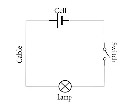
- Electrical circuit diagrams, also known as schematics, are graphical representations of electrical circuits using standardized symbols. These diagrams convey the relationships between components and the flow of electrical current within a circuit. There are different types of circuit diagrams, including schematic diagrams, wiring diagrams, and block diagrams.
Schematic Diagrams:
- Schematic diagrams provide a detailed representation of individual components and their connections within a circuit.
- They are commonly used for complex electronic circuits, control systems, and integrated circuits.
- Schematic diagrams are essential for circuit design, analysis, and troubleshooting.
Wiring Diagrams:
- Wiring diagrams focus on the physical layout of components and their interconnections within a system.
- They are often used in the automotive industry, household electrical wiring, and building control systems.
- Wiring diagrams help technicians understand how to physically wire a circuit.
Block Diagrams:
- Block diagrams provide a high-level overview of a system or circuit.
- They use blocks to represent major components or subsystems and arrows to indicate the flow of signals or information between them.
- Block diagrams are useful for understanding the functional relationships within a complex system.
4. How to Read Electrical Symbols
- Reading electrical symbols and understanding their meanings is crucial for interpreting circuit diagrams. Here are some key principles for reading electrical symbols effectively:
- Identifying Components and Their Functions:
- Familiarize yourself with common electrical symbols and their corresponding components.
- Understand the functions of each component, including passive and active elements, sources, and connectors.
Analyzing Circuit Connections:
- Follow the lines and connections in the diagram to trace the path of electrical current.
- Note the direction of arrowheads, which indicate the flow of signals or currents.
- Pay attention to the labels and annotations to understand component values, such as resistance or voltage.
Referencing a Key:
- Some circuit diagrams include a key or legend that provides explanations for symbols used in the diagram.
- Refer to the key when encountering unfamiliar symbols or components.
Consider Context:
- Analyze the overall context of the circuit and the specific function it is designed to perform.
- Take into account the purpose of the circuit, whether it’s for amplification, control, signal processing, or power distribution.
5. Applications and Industries
- Electrical circuit diagrams and symbols find applications in various industries and sectors, each with its specific requirements and standards:
Residential Electrical Wiring:
- In residential settings, electrical symbols are used in house wiring diagrams to plan and install electrical systems safely.
- These diagrams ensure that electrical connections meet building codes and safety standards.
Automotive Electronics:
- Electrical symbols are prevalent in automotive wiring diagrams, enabling technicians to diagnose and repair electrical issues in vehicles.
- Modern automobiles rely on complex electrical systems for engine control, infotainment, lighting, and safety features.
Industrial Control Systems:
- Industrial circuits often employ complex control systems with sensors, actuators, and programmable logic controllers (PLCs).
- Electrical symbols help engineers design and maintain industrial control systems used in manufacturing and process industries.
Telecommunications:
- The telecommunications industry uses circuit diagrams for designing and troubleshooting communication systems, including network infrastructure and mobile devices.
Aerospace and Avionics:
- Avionics systems on aircraft, spacecraft, and drones heavily rely on electrical symbols and diagrams to ensure reliable communication, navigation, and control.
6. Designing Electrical Circuits
- Designing electrical circuits involves creating schematics, selecting components, and ensuring the circuit meets specific requirements. Engineers use specialized software tools for circuit design and simulation. Some common steps in designing electrical circuits include:

Circuit Design Software:
- Engineers use software tools like AutoCAD Electrical, Eagle, OrCAD, and KiCad to create schematic diagrams, simulate circuit behavior, and generate Bill of Materials (BOM).
Prototyping and Testing:
- After designing a circuit on paper or in software, engineers often build prototypes to test and verify its functionality.
- Prototyping involves selecting physical components, creating a physical circuit, and conducting tests.
Iterative Design:
- Engineers may go through multiple iterations of circuit design and testing to optimize performance, reduce costs, or address specific requirements.
7. Safety Considerations
- Working with electrical circuits presents inherent hazards, including electrical shock, fire, and equipment damage. To ensure safety, electrical diagrams and components may include safety symbols and labels. These symbols warn about potential dangers and provide guidance on safe practices.
Electrical Hazards:
- Electrical hazard symbols indicate the presence of electrical energy and warn individuals to take precautions.
- Symbols for high voltage, electrical shock, and grounding are common safety symbols.
Safety Symbols:
Safety symbols on electrical components or equipment may include information on safe operation, such as voltage limits and safety instructions.
Safety Precautions:
- When working with electrical circuits, always follow safety protocols, wear appropriate personal protective equipment (PPE), and disconnect power sources before handling electrical components.
8. Conclusion
- Electrical symbols play a crucial role in electrical engineering, electronics, and many other industries where electrical circuits are designed, analyzed, and maintained. These symbols provide a standardized and universally understood means of representing components and connections within circuits, simplifying communication among professionals worldwide.
- From the residential wiring in our homes to the intricate systems powering advanced technologies, electrical symbols and circuit diagrams are at the heart of modern electrical and electronic systems. As technology continues to advance, the need for clear and standardized electrical symbols remains vital in ensuring the safety, reliability, and efficiency of electrical circuits and systems.
Read More
- Difference Between Watts And Volts
- Molar Mass Of Sulphur
- Electronics In Daily Life
- Molecular Weight Of Hcl
- Asteroid And Comet Difference
Frequently Asked Questions (FAQs) Electric Circuit Electrical Symbols
1. What are electric circuit electrical symbols, and why are they important?
Electric circuit electrical symbols are graphical representations of electrical and electronic components used in circuit diagrams. They are essential for communicating circuit designs and concepts effectively. Standardized symbols ensure clarity, consistency, and precision in circuit diagrams.
2. How do electric circuit electrical symbols simplify circuit design and analysis?
Electric circuit electrical symbols simplify circuit design and analysis by providing a universal language for representing components. Engineers and technicians can quickly understand and work with circuit diagrams, making it easier to design, troubleshoot, and maintain electrical systems.
3. Where can I find a comprehensive list of electric circuit electrical symbols and their meanings?
You can find comprehensive lists of electric circuit electrical symbols, along with their meanings, in electrical engineering textbooks, online resources, and dedicated symbol libraries in circuit design software. These resources typically include symbols for passive components, active components, power sources, connectors, switches, and more.
4. Are there international standards for electric circuit electrical symbols?
Yes, there are international standards for electric circuit electrical symbols. Organizations like the International Electrotechnical Commission (IEC) and the Institute of Electrical and Electronics Engineers (IEEE) have established standardized symbols to ensure consistency in circuit diagrams worldwide. These standards facilitate cross-border communication and understanding.
5. How do I interpret circuit diagrams that use electric circuit electrical symbols?
Interpreting circuit diagrams involves understanding the meanings of electrical symbols and tracing the path of electrical current through the diagram. Key principles include identifying components, recognizing connections, following the flow of signals or currents, and considering the context and purpose of the circuit.