

Discover comprehensive NCERT Science Electricity of Class 10 Chapter 12 Solutions containing well-explained answers to all the exercise questions found in your textbook. These solutions cover a wide range of topics, including electric cells, electric bulbs, electric circuits, switches, conductors, insulators, as well as examples of each.
You’ll encounter diverse question formats such as ‘Fill in the Blanks’, ‘True or False’, circuit diagrams, and descriptive answering questions, which will facilitate a deeper understanding of the concepts.
In this article, we will explore the very essence of electricity, from its historical roots and foundational principles to practical applications in our daily lives and cutting-edge technologies. Whether you’re just beginning your journey into the realm of electrical knowledge or seeking to reinforce your existing understanding, we have tailored this article to cater to all learning levels.
Electricity of Class 10 NCERT Science Chapter 11 Solutions

Electricity of Class 10
NCERT Electricity of Class 10 Science Chapter 11 Solutions
1. What does an electric circuit mean?
Answer:
An electric circuit refers to a seamless, unbroken loop comprising electric components, allowing the flow of an electric current. The fundamental elements of a basic circuit include:
(a) Conductors – These materials facilitate the easy movement of electric charges, enabling the flow of current within the circuit.
(b) Cell – The cell, acting as a power source, provides the necessary electric potential that propels the electrons to move through the circuit.
(c) Switch – A switch serves as a control device within the circuit, allowing us to open or close the path for the electric current, thus controlling its flow.
(d) Load – The load represents any device or component in the circuit that consumes electrical energy, converting it into various forms of useful output, such as light, heat, or motion.
2. Define the unit of current.
Answer:
The unit of current is known as the ampere. An ampere is defined as the rate of flow of one coulomb of electric charge per second.
3. Calculate the number of electrons constituting one coulomb of charge.
Answer:
The charge of an electron is determined to be 1.6 × 10^-19 C.
Based on the principle of charge quantization, the charge (Q) can be expressed as Q = n * qe, where ‘n’ represents the number of electrons, and ‘qe’ is the charge of an electron.
By substituting the given values into the above equation, we can calculate the number of electrons in one coulomb of charge as follows:
n = 1 C/1.6 * 10^-19 = 6.25 * 10^18
Consequently, the number of electrons comprising one coulomb of charge is found to be 6.25 × 10^18.
4. Name a device that helps to maintain a potential difference across a conductor.
Answer:
One of the devices responsible for sustaining a potential difference across a conductor is a battery, which comprises one or more electric cells.
5. What is meant by saying that the potential difference between two points is 1 V?
Answer:
The potential difference between two points is defined as 1 volt (V) when 1 joule (J) of work is expended to move a charge of 1 coulomb (C) from one point to another.
6. How much energy is given to each coulomb of charge passing through a 6 V battery?
Answer:
As per the potential difference equation:
V = W / Q, where:
V represents the potential difference between two points,
W is the work done in moving the charge from one point to another,
Q denotes the charge.
Using the above equation, we can determine the energy imparted to each coulomb:
W = V × Q
Upon substituting the given values into the equation, we find:
W = 6V × 1C = 6 J
Therefore, when passing through a 6 V battery, each coulomb of charge receives 6 joules of energy.
7. On what factors does the resistance of a conductor depend?
Answer:
The resistance of a conductor is influenced by the following factors:
a. Temperature of the conductor: The resistance tends to change with variations in the conductor’s temperature.
b. Cross-sectional area of the conductor: A larger cross-sectional area typically results in reduced resistance.
c. Length of the conductor: Longer conductors generally have higher resistance compared to shorter ones.
d. Nature of the material of the conductor: The resistance is determined by the specific material properties of the conductor. Different materials have different inherent resistances.
8. Will current flow more easily through a thick wire or a thin wire of the same material, when connected to the same source? Why?
Answer:
The resistance of a wire can be calculated using the formula:
R = ρ * l / A
where:
ρ represents the resistivity of the wire’s material,
l is the length of the wire, and
A denotes the cross-sectional area of the wire.
As we observe from the equation, the cross-sectional area of the wire is inversely proportional to its resistance. Consequently, a thinner wire exhibits higher resistance, while a thicker wire offers lower resistance. Therefore, current flows more effortlessly through a thick wire as compared to a thin wire.
9. Let the resistance of an electrical component remain constant while the potential difference across the two ends of the component decreases to half of its former value. What change will occur in the current through it?
Answer:
Ohm’s Law provides a means to calculate the change in the current flowing through an electrical component. According to Ohm’s Law, the current (I) can be determined by the equation:
I = V / R
Now, if we reduce the potential difference by half while keeping the resistance constant, we get:
New voltage: V’ = V / 2
New resistance: R’ = R
Let the new amount of current be denoted as I’.
We can determine the change in the current using Ohm’s Law as shown below:
NCERT Solutions for Class 10 Chapter 12 Image 2
Thus, the current flowing through the electrical component is reduced by half when the potential difference is halved while keeping the resistance constant.
10. Why are coils of electric toasters and electric irons made of an alloy rather than a pure metal?
Answer:
Alloys possess significantly higher melting points compared to pure metals due to their elevated resistivity. This inherent property allows alloys to resist melting easily at high temperatures.
As a result, alloys find extensive application in heating appliances, such as electric toasters and electric irons, where they can endure and maintain their structural integrity even when subjected to elevated temperatures.
11. Use the data in the table given below and answer the following questions.
a. Which among iron and mercury is a better conductor?
b. Which material is the best conductor?
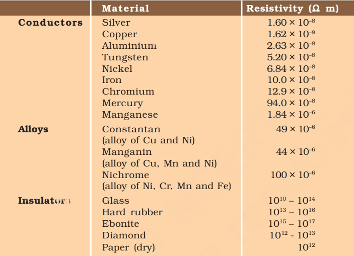

Answer
a. Iron exhibits better conductivity than mercury due to the lower resistivity of iron when compared to mercury.
b. Among all the materials listed in the table, silver stands out as the best conductor as it possesses the lowest resistivity of all, measuring at 1.60 × 10^-8.
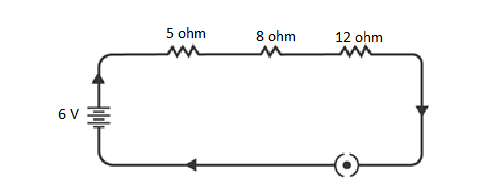
12. Draw a schematic diagram of a circuit consisting of a battery of three cells of 2 V each, a 5 Ω resistor, an 8 Ω resistor, and a 12 Ω resistor, and a plug key, all connected in series.
“A set of three cells, each having a voltage of 2 V, combines to form a battery with a total potential of 6 V. The circuit illustration provided depicts three resistors with resistances of 12 Ω, 8 Ω, and 5 Ω, connected in a series arrangement, along with the 6 V potential battery.”

Q 13. Redraw the circuit of Question 1, putting in an ammeter to measure the current through the resistors and a voltmeter to measure the potential difference across the 12 Ω resistor. What would be the readings in the ammeter and the voltmeter?
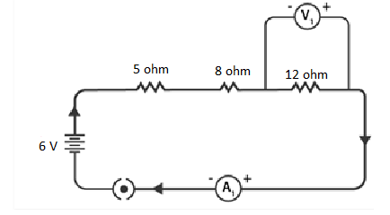

To measure current and potential difference in a circuit, it is important to connect the ammeter in series with the resistors and the voltmeter in parallel to the resistor, as depicted in the figure below.
NCERT Solutions for Class 10 Chapter 12 Image 4
By utilizing Ohm’s Law, the readings of the ammeter and the voltmeter can be determined.
The total resistance of the circuit is obtained by adding the individual resistances: 5 Ω + 8 Ω + 12 Ω = 25 Ω.
Given that the potential difference of the circuit is 6 V, the current flowing through the circuit (or the resistors) can be calculated as follows:
I = V / R = 6 V / 25 Ω = 0.24 A
Let the potential difference across the 12 Ω resistor be denoted as V1.
Using the obtained current, V1 can be calculated as follows:
V1 = I × 12 Ω = 0.24 A × 12 Ω = 2.88 V
Hence, the ammeter reading will be 0.24 A, and the voltmeter reading will be 2.88 V.
Q 14. Judge the equivalent resistance when the following are connected in parallel – (a) 1 Ω and 106 Ω, (b) 1 Ω, 103 Ω, and 106 Ω.
When 1 Ω and 106 are connected in parallel, the equivalent resistance is given by


Therefore, the equivalent resistance is 1 Ω.
(b) When 1 Ω, 103 Ω, and 106 Ω are connected in parallel, the equivalent resistance is given by


Therefore, the equivalent resistance is 0.999 Ω.
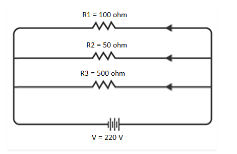
Q 15. An electric lamp of 100 Ω, a toaster of resistance 50 Ω, and a water filter of resistance 500 Ω are connected in parallel to a 220 V source. What is the resistance of an electric iron connected to the same source that takes as much current as all three appliances, and what is the current through it?
The circuit diagram illustrates the electric lamp, toaster, and water filter connected in parallel to a 220 V power source, as shown below:

NCERT Solutions for Class 10 Chapter 12 Image 7
To determine the equivalent resistance of the resistors in the circuit, follow these calculations:
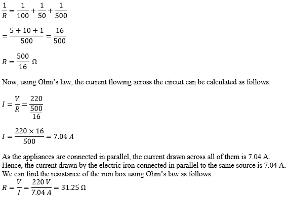

NCERT Solutions for Class 10 Chapter 12 Image 8
Furthermore, the resistance of the electric iron box is measured to be 31.25 Ω.
Q 16. What are the advantages of connecting electrical devices in parallel with the battery instead of connecting them in series?
When electrical devices are connected in parallel, the voltage across each appliance remains the same and is equal to the supply voltage. In this configuration, there is no division of voltage among the appliances. Each device receives the full potential difference of the source.
Additionally, connecting devices in parallel reduces the effective resistance of the circuit. The equivalent resistance of the parallel configuration is lower than the individual resistances of the devices. This leads to an increase in the total current flowing through the circuit, as the path for current is effectively widened by the parallel arrangement of appliances.
Q 17. How can three resistors of resistances 2 Ω, 3 Ω, and 6 Ω be connected to give a total resistance of (a) 4 Ω, (b) 1 Ω?
In the first circuit diagram shown below, three resistors are connected:
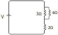

It can be observed that the resistors of 3 Ω and 6 Ω are connected in parallel. Their equivalent resistance can be calculated as follows:
![]()


The equivalent resistor of 2 Ω is then connected in series with another 2 Ω resistor. Consequently, the equivalent resistance of this combination can be calculated as follows:
Req = 2 Ω + 2 Ω = 4 Ω
Thus, the total resistance of the circuit is 4 Ω.
(b) In the second circuit diagram displayed below, three resistors are connected:
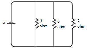

It is evident that all the resistors are connected in parallel. Therefore, their equivalent resistance can be calculated as follows:
![]()

The total resistance of the circuit is 1 Ω.
Q 18. What is (a) the highest, (b) the lowest total resistance that can be secured by combinations of four coils of resistance 4 Ω, 8 Ω, 12 Ω, 24 Ω?
(a) When the four resistors are connected in series, their total resistance will be the sum of their individual resistances, and it will be the highest. The total equivalent resistance of the resistors connected in series will be 4 Ω + 8 Ω + 12 Ω + 24 Ω = 48 Ω.
(b) If the resistors are connected in parallel, their equivalent resistance will be the lowest. The total equivalent resistance connected in parallel is:


Therefore, the lowest total resistance is 2 Ω.
Q 19. Why does the cord of an electric heater not glow while the heating element does?
The heating element in an electric heater is constructed using an alloy with high resistance. When electricity passes through the heating element, it generates significant heat, causing the element to glow red.
In contrast, the cord connecting the heater is typically made of materials like copper or aluminum, which have low resistance. As a result, the cord does not heat up enough to glow since the low resistance allows the electricity to flow through it smoothly without generating excessive heat.
Q 20. Compute the heat generated while transferring 96000 coulomb of charge in one hour through a potential difference of 50 V.
Given the following values:
Charge, Q = 96000 C
Time, t = 1 hr = 60 x 60 = 3600 s
Potential difference, V = 50 volts
Now, to calculate the current (I), we can use the formula:
I = Q / t
where Q is the charge, and t is the time.
Therefore, I = 96000 C / 3600 s = 80/3 A
Now, we can find the amount of heat generated (H) using Joule’s law:
H = V * I * t
H = 50 V * (80/3 A) * 3600 s = 4.8 x 10^6 J
Thus, the heat generated is approximately 4.8 x 10^6 joules.
Q 21. An electric iron of resistance 20 Ω takes a current of 5 A. Calculate the heat developed in 30 s.
The quantity of heat generated can be determined using Joule’s law of heating, given by the equation:
H = VIt
By substituting the given values into the equation, we find:
H = 100 × 5 × 30 = 1.5 × 10^4 J
Thus, the amount of heat developed by the electric iron in 30 seconds is 1.5 × 10^4 joules.
Q 22. What determines the rate at which energy is delivered by a current?
Electric power refers to the rate at which electrical energy is consumed by electric appliances. Consequently, it represents the rate at which energy is delivered by a current to the appliance.
Q 23. An electric motor takes 5 A from a 220 V line. Determine the power of the motor and the energy consumed in 2 h.
The power of the motor can be determined using the equation:
P = VI
By substituting the given values into the equation, we find:
P = 220 V × 5 A = 1100 W
Thus, the power of the motor is 1100 watts.
The energy consumed by the motor can be calculated using the equation:
E = P × T
By substituting the given values into the equation, we find:
E = 1100 W × 7200 s = 7.92 × 10^6 J
Therefore, the energy consumed by the motor in 2 hours is 7.92 × 10^6 joules.
Q 24. A piece of wire of resistance R is cut into five equal parts. These parts are then connected in parallel. If the equivalent resistance of this combination is R′, then the ratio R/R′ is _____.
(a) 1/25
(b) 1/5
(c) 5
(d) 25
Answer:
The original resistance is divided into five equal parts, which means each part has a resistance of R/5.
Since each part is connected to one another in parallel, the equivalent resistance (R’) can be calculated as shown below:
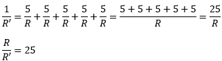

The ratio of R to R’ is 25.
Q 26. Which of the following does not represent electrical power in a circuit?
(a) I2R
(b) IR2
(c) VI
(d) V2/R
Answer:
Electrical power is expressed by the equation P = VI. (1)
According to Ohm’s law, V = IR.
By substituting the value of V in equation (1), we obtain:
P = (IR) × I
P = I^2R
Similarly, from Ohm’s law, I = V/R.
Substituting the value of I in equation (1), we get:
P = V × V/R = V^2/R
From this, it is evident that the expression IR^2 does not represent electrical power in a circuit. Instead, the correct representation is V^2/R.
Q 27. An electric bulb is rated 220 V and 100 W. When it is operated on 110 V, the power consumed will be _____.
(a) 100 W
(b) 75 W
(c) 50 W
(d) 25 W
The energy consumed by the appliance can be determined by the expression:
P = VI = V^2/R
The resistance of the light bulb can be calculated as follows:
R = V^2/P
By substituting the values, we find:
R = (220)^2 / 100 = 484 Ω
Even if the supply voltage is reduced, the resistance remains the same. Hence, the power consumed can be calculated as follows:
P = V^2 / R
Substituting the value, we get:
P = (110)^2 V / 484 Ω = 25 W
Thus, the power consumed when the electric bulb operates at 110 V is 25 W.
Q 28. Two conducting wires of the same material and of equal lengths and equal diameters are first connected in series and then parallel in a circuit across the same potential difference. The ratio of heat produced in series and parallel combinations would be _____.
(a) 1:2
(b) 2:1
(c) 1:4
(d) 4:1
Answer:
(c) 1:4
Q 29. How is a voltmeter connected in the circuit to measure the potential difference between two points?
To measure the voltage between any two points, the voltmeter should be connected in parallel across the two points.
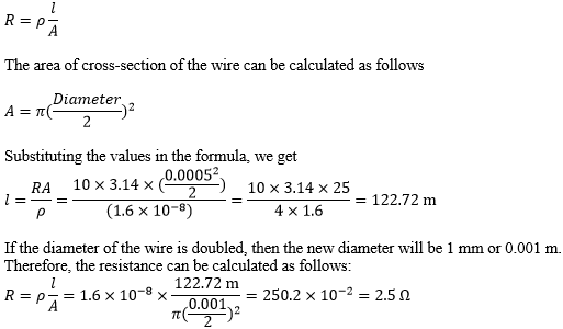
Q 30. A copper wire has diameter 0.5 mm and resistivity of 1.6 × 10⁻⁸ Ω m. What will be the length of this wire to make its resistance 10 Ω? How much does the resistance change if the diameter is doubled?

Q 31. The values of current I flowing in a given resistor for the corresponding values of potential difference V across the resistor are given below –
| I (Ampere) | 0.5 | 1.0 | 2.0 | 3.0 | 4.0 |
| V (Volts) | 1.6 | 3.4 | 6.7 | 10.2 | 13.2 |
Plot a graph between V and I and calculate the resistance of that resistor.
The plot depicting the relationship between voltage and current is known as the IV characteristic. The current is represented on the y-axis, while the voltage is shown on the x-axis. The table provides various current values corresponding to different voltage values. The IV characteristic for the given resistor is illustrated below.
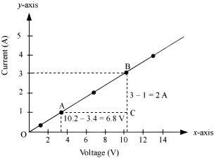

The value of resistance can be obtained from the slope of the line.
The slope is calculated as follows:
Slope = 1/R = BC/AC = 2/6.8
To calculate R:
R = 6.8/2 = 3.4 Ω
Thus, the resistance of the resistor is 3.4 Ω.
Q 32. When a 12 V battery is connected across an unknown resistor, there is a current of 2.5 mA in the circuit. Find the value of the resistance of the resistor.
The resistance (R) of a resistor is determined by Ohm’s law, which states V = IR.
To find R, we use the formula R = V/I, where:
Potential difference, V = 12 V
Current in the circuit, I = 2.5 mA = 2.5 x 10^-3 A
Therefore, the resistance of the resistor is 4.8 kΩ.
Q 33. A battery of 9 V is connected in series with resistors of 0.2 Ω, 0.3 Ω, 0.4 Ω, 0.5 Ω and 12 Ω, respectively. How much current would flow through the 12 Ω resistor?
In a series connection, there is no division of current, and the same current flows across all the resistors.
To calculate the amount of current flowing through the resistors, we can use Ohm’s law.
First, let’s determine the equivalent resistance of the series connection:
R = 0.2 Ω + 0.3 Ω + 0.4 Ω + 0.5 Ω + 12 Ω = 13.4 Ω
Now, applying Ohm’s law:
![]()

The current flowing through the 12 Ω resistor is 0.671 A.
Q 34. How many 176 Ω resistors (in parallel) are required to carry 5 A on a 220 V line?
Let’s assume that “n” 176 Ω resistors are connected in parallel.
The formula for calculating the equivalent resistance (Req) of “n” resistors connected in parallel is:
1/Req = 1/R₁ + 1/R₂ + 1/R₃ + … + 1/Rₙ
where R₁, R₂, R₃, …, Rₙ are the individual resistances.
Given that the current (I) is 5 A and the voltage (V) is 220 V, and we want to find the number of 176 Ω resistors (n).
First, let’s find the equivalent resistance (Req) using Ohm’s law:
V = I * Req
Req = V / I Req = 220 V / 5 A Req = 44 Ω
Now, we can calculate the number of resistors (n) using the equivalent resistance:
1/Req = 1/176 Ω + 1/176 Ω + … + 1/176 Ω (n times)
1/44 Ω = n/176 Ω
n = 4
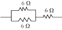
Q 35. Show how you would connect three resistors, each of resistance 6 Ω, so that the combination has a resistance of (i) 9 Ω, (ii) 4 Ω.
If we connect the resistors in series, the equivalent resistance will be the sum of the resistors, i.e., 6 Ω + 6 Ω + 6 Ω = 18 Ω, which is not the desired outcome. If we connect them in parallel, the equivalent resistance will be 6/2 = 3 Ω, which is also not desired. Thus, we need to explore other combinations to achieve the desired total resistance.
(a) Two resistors in parallel:

Two 6 Ω resistors are connected in parallel. Their equivalent resistance will be:
1/Req = 1/6 Ω + 1/6 Ω
1/Req = 2/6 Ω
Req = 6/2 = 3 Ω
The third 6 Ω resistor is in series with 3 Ω. Hence, the equivalent resistance of the circuit is 6 Ω + 3 Ω = 9 Ω.
(b) Two resistors in series:
![]()

Two 6 Ω resistors are in series. Their equivalent resistance will be the sum: 6 Ω + 6 Ω = 12 Ω.
The third 6 Ω resistor is in parallel with 12 Ω. Hence, the equivalent resistance will be:
1/Req = 1/6 Ω + 1/12 Ω
1/Req = 3/12 Ω
Req = 12/3 = 4 Ω
Therefore, the total resistance of the circuit is 4 Ω.
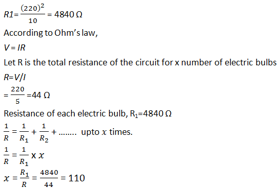
Q 36. Several electric bulbs designed to be used on a 220 V electric supply line, are rated 10 W. How many lamps can be connected in parallel with each other across the two wires of 220 V line if the maximum allowable current is 5 A?
The resistance (R1) of the bulb is given by the expression:
R1 = V^2 / P
Where:
Supply voltage, V = 220 V
Rating of the electric bulb, P = 10 watts
Since R = V^2 / P, we can substitute the given values to find R1.

Q 37. A hot plate of an electric oven connected to a 220 V line has two resistance coils A and B, each of 24 Ω resistance, which may be used separately, in series, or in parallel. What are the currents in the three cases?
Case (i) When coils are used separately:
Using Ohm’s law, we can calculate the current flowing through each coil as follows:
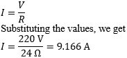

When used separately, 9.166 A of current flows through each resistor.
Case (ii) When coils are connected in series:
The total resistance in the series circuit is 24 Ω + 24 Ω = 48 Ω
The current flowing through the series circuit is calculated as follows:
![]()

Therefore, a current of 4.58 A flows through the series circuit.
Case (iii) When coils are connected in parallel:
When the coils are connected in parallel, the equivalent resistance is calculated as follows:
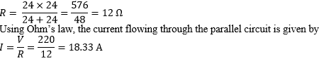

The current in the parallel circuit is 18.33 A.
Q 38. Compare the power used in the 2 Ω resistor in each of the following circuits: (i) a 6 V battery in series with 1 Ω and 2 Ω resistors, and (ii) a 4 V battery in parallel with 12 Ω and 2 Ω resistors.
(i) When the potential difference is 6 V and the resistors 1 Ω and 2 Ω are connected in series, their equivalent resistance is given by 1 Ω + 2 Ω = 3 Ω. The current in the circuit can be calculated using Ohm’s law as follows:
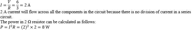

Therefore, the power consumed by the 2 Ω resistor is 8 W.
(ii) When 12 Ω and 2 Ω resistors are connected in parallel, the voltage across the resistors remains the same. Knowing that the voltage across the 2 Ω resistor is 4 V, we can calculate the power consumed by the resistor as follows:
![]()

The power consumed by the 2 Ω resistor is 8 W.
Q 39. Two lamps, one rated 100 W at 220 V, and the other 60 W at 220 V, are connected in parallel to electric mains supply. What current is drawn from the line if the supply voltage is 220 V?
As both bulbs are connected in parallel, the voltage across each of them will be the same.
The current drawn by the bulb with a rating of 100 W can be calculated using the formula:
P = V × I
I = P / V
Substituting the given values, we get:
I = 100 W / 220 V = 100/220 A
Similarly, the current drawn by the bulb with a rating of 60 W can be calculated as follows:
I = 60 W / 220 V = 60/220 A
Therefore, the total current drawn from the line is:
![]()

Q 40. Which uses more energy, a 250 W TV set in 1 hr, or a 1200 W toaster in 10 minutes?
The energy consumed by electrical appliances is determined by the equation:
H = Pt, where P is the power of the appliance, and t is the time.
Using this formula, we can calculate the energy consumed by a TV with a power rating of 250 W as follows:
H = 250 W × 3600 seconds = 9 × 10^5 J
Similarly, the energy consumed by a toaster with a power rating of 1200 W is:
H = 1200 W × 600 s = 7.2 × 10^5 J
From the calculations, it can be observed that the energy consumed by the TV is greater than the toaster.
Q 41. An electric heater of resistance 8 Ω draws 15 A from the service mains 2 hours. Calculate the rate at which heat is developed in the heater.
The rate at which heat develops in the heater can be calculated using the following formula:
P = I^2 * R
By substituting the given values into the equation, we find:
P = (15A)^2 * 8 Ω = 1800 watts
Therefore, the electric heater produces heat at the rate of 1800 watts.
Q 42. Explain the following.
a. Why is the tungsten used almost exclusively for filament of electric lamps?
b. Why are the conductors of electric heating devices, such as bread-toasters and electric irons, made of an alloy rather than a pure metal?
c. Why is the series arrangement not used for domestic circuits?
d. How does the resistance of a wire vary with its area of cross-section?
e. Why copper and aluminium wires are usually employed for electricity transmission?
a. Tungsten is an ideal choice for the filament of electric lamps due to its high resistivity and melting point. These properties prevent it from burning readily when heated, making it suitable for operating at high temperatures in electric lamps.
b. Alloys are preferred as conductors for electric heating devices because of their high resistivity. Compared to pure metals, alloys have higher resistivity, leading to the generation of a substantial amount of heat when current passes through them, which is crucial for heating applications.
c. The series arrangement is not commonly used for domestic circuits due to the following reasons:
– The overall voltage gets divided in a series circuit, which may cause electric appliances not to receive their rated power for proper operation.
– All connected appliances in a series circuit cannot be operated independently. If one device is defective, the entire circuit will be affected.
– The total resistance increases in a series circuit, leading to reduced current flow, which may cause appliances to operate inefficiently.
d. Resistance is inversely proportional to the area of cross-section. When the area of the cross-section increases, the resistance decreases, and vice versa. This relationship between resistance and the cross-sectional area is an important factor to consider in electrical circuits and material design.
e. Copper and aluminum are widely used for electricity transmission due to their low resistivity and excellent conductivity. Their low resistivity results in significantly less power losses in the form of heat during the transmission of electricity, making them efficient choices for power transmission applications.
Electricity of Class 10 NCERT Science Chapter 11 Solutions
Chapter 11 – Electricity in Class 10 Science is an essential topic carrying at least 8 marks as per previous examination trends. However, the 2018 Class 10 Science exam had questions totalling up to 7 marks for this chapter. To strengthen your understanding of the key concepts in this chapter, make use of NCERT Solutions for Class 10.
The topics covered in the NCERT Solutions for Class 10 Science, Chapter 11 are as follows:
1. Ohm’s law
2. Resistivity and Resistance
3. Factors affecting the Resistance of a Conductor
4. Parallel and Series Combination of Resistors and their applications
5. Heating Effect of Electric Current and its Applications
6. Electric Power
7. The interrelation between P, V, I, and R
Electricity is a vital aspect of our society, shaping our civilization since the industrial revolution. It powers entire industries and businesses, and life without electricity would result in chaos, given its importance as a source of energy.
Through NCERT Solutions for Class 10 Science, you can explore how electricity works at the molecular level, understand crucial concepts, and discover its practical applications. The learning resources are designed to facilitate efficient learning.
Key Features of NCERT Solutions for Class 10 Science, Chapter 11 – Electricity:
– Content presented in an easy-to-understand language
– Solutions crafted by highly qualified teachers and industry experts
– Additional questions based on the latest prescribed syllabus
– Detailed explanations of challenging exam questions
– Access to additional learning resources like sample papers and previous year question papers
Read Also:
- NCERT Solutions Science Class 10 All Chapter
- Our Environment Class 10 Chapter 13 Solution for NCERT
- Chemical Equations and Reactions Class 10: Solution of Sci. Ch.1
Frequently Asked Question – FAQs on Electricity of Class 10 NCERT Science Chapter 11 Solutions
Q 1. What are the 4 types of electricity?
The four types of electricity are static electricity (buildup of charge due to friction), current electricity (flow of charge through conductors), direct current (DC, flows in one direction), and alternating current (AC, changes direction periodically, commonly used in household electricity).
Q 2. What is electricity in class 10?
In Class 10, electricity is a crucial topic in the Science curriculum. Students learn about the behavior of electric currents, Ohm’s law, resistance, and the heating effect of electric current. They also study the concepts of parallel and series combinations of resistors, as well as the relationship between power, voltage, current, and resistance.
Q 3. What is electricity and its formula?
Electricity is a form of energy resulting from the movement of electric charge. It involves the flow of electrons through conductive materials like wires. The formula for calculating electrical power (P) is P = VI, where V represents voltage (potential difference) and I denotes current flowing through the conductor.